A primer in high voltage electronics
I began working on high voltage electronics in order to control the high voltage soft electro hydraulic actuators I was building. This was the beginning of my Ph.D. and I was a noob for anything high voltage. Over time I learned a lot. Here is a crude summary of things I tinkered with to begin with and afterwards developed in a more rigorous manner.
Part 1: Bulky old high voltage DC power supply
Below is an old and bulky DC high voltage power supply I was able to scavenge from ebay (the last servicing date on its label was 1984! Repairing it gave a first understanding of the high voltage electronics and belief that they could be simple in basic units.
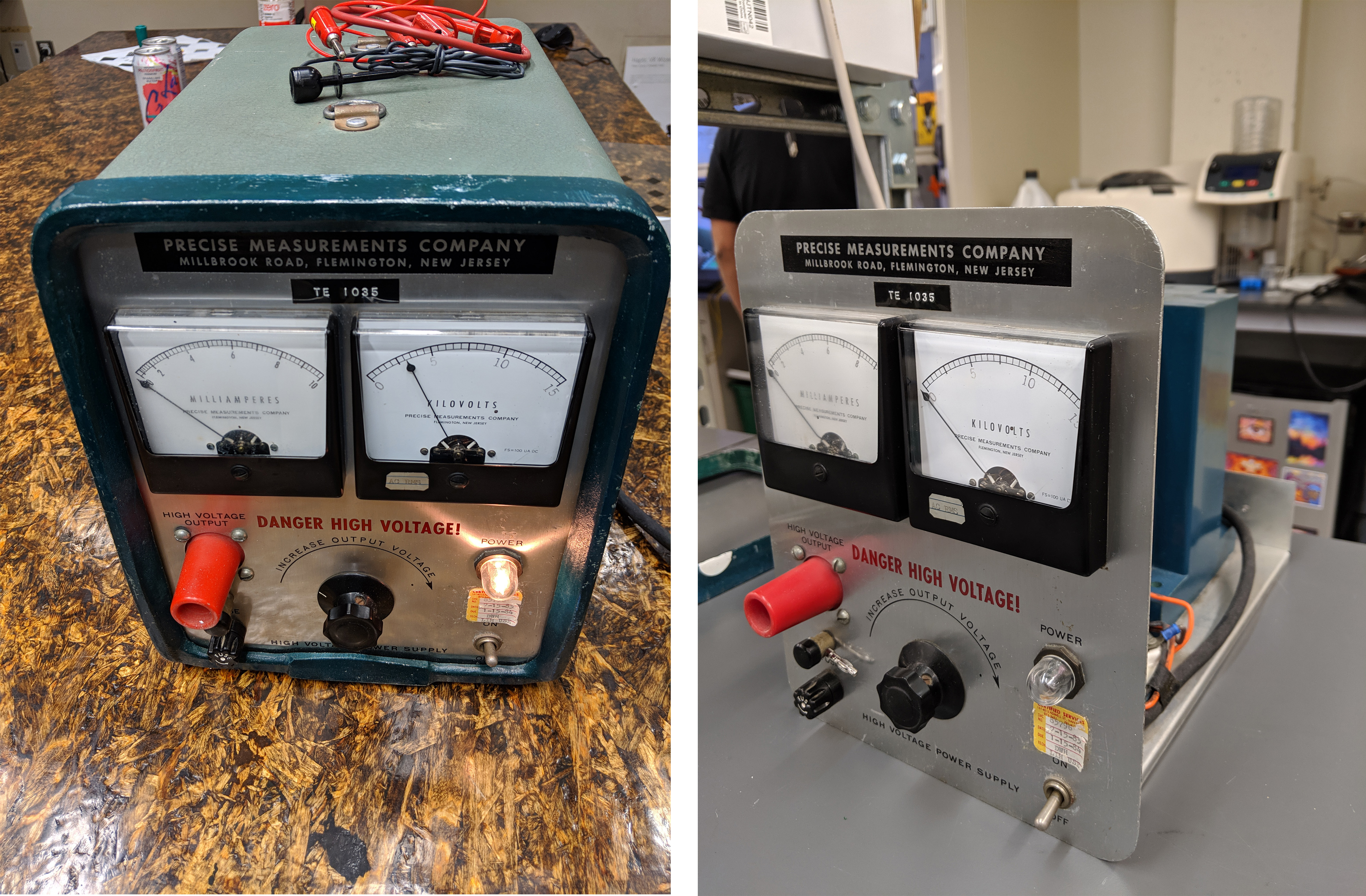
An old high voltage (0-15 kV) DC power supply I got from ebay.
This power supply had an input voltage of 110-250V AC at 50/60 Hz. Afterwards, inside the power supply, it passed through an electric ballast (the ones earlier used in fluorescent light bulbs) to limit the current. The current limited AC signal was feeded to the transformer which stepped it up to the desirable voltage. Afterwards, a simple full wave rectifier and you had the high voltage (DC) output. It ofcourse had peripheral components like the ON/OFF indicator, voltmeter and ammeter.
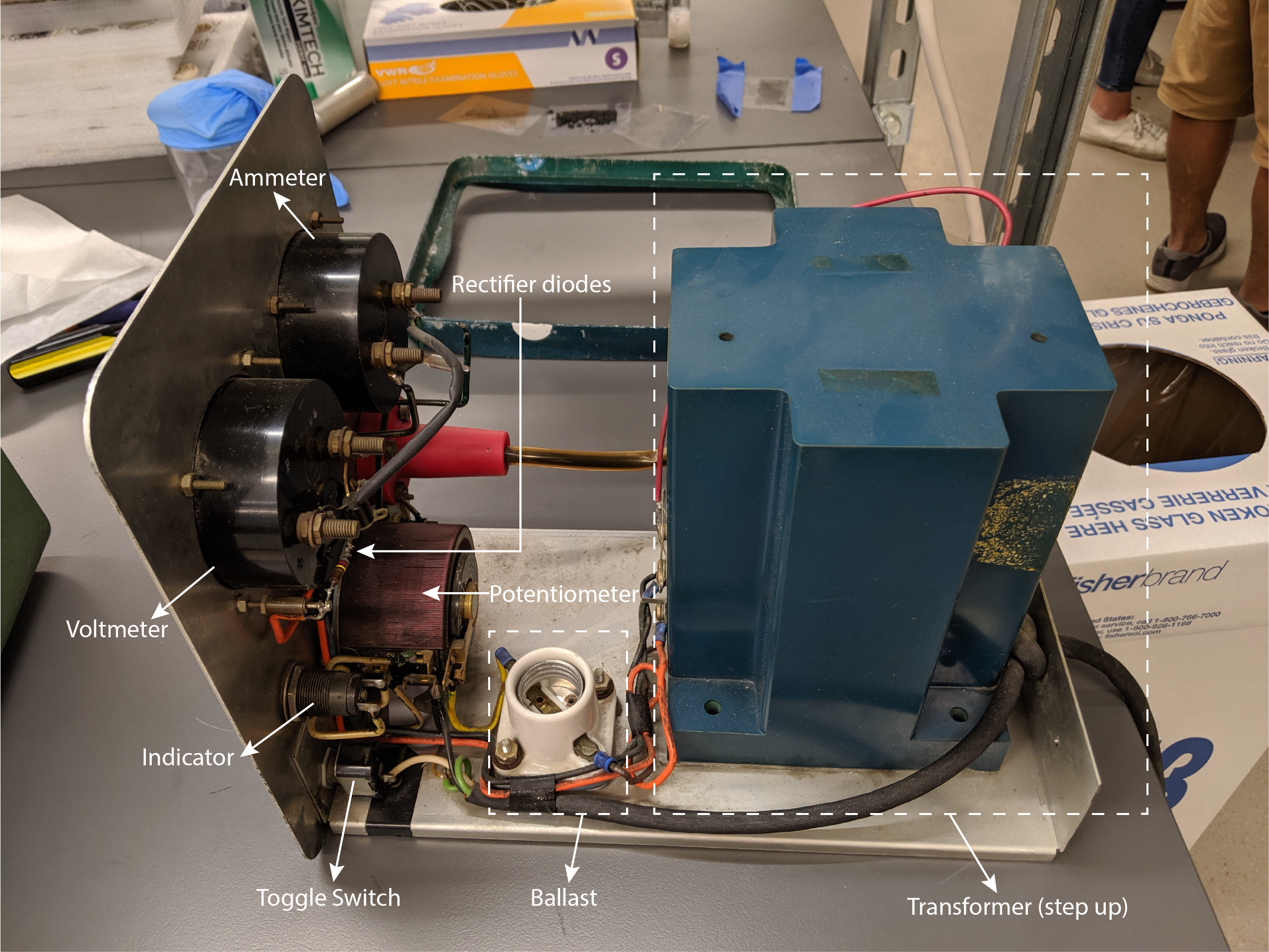
The high voltage power supply is bulky but cinsists of relatively simple components like a ballast, step up trasformer and a full-wave rectifier.
Part 2: Quick hack for a portable high voltage power supply using a DC-DC voltage amplifier
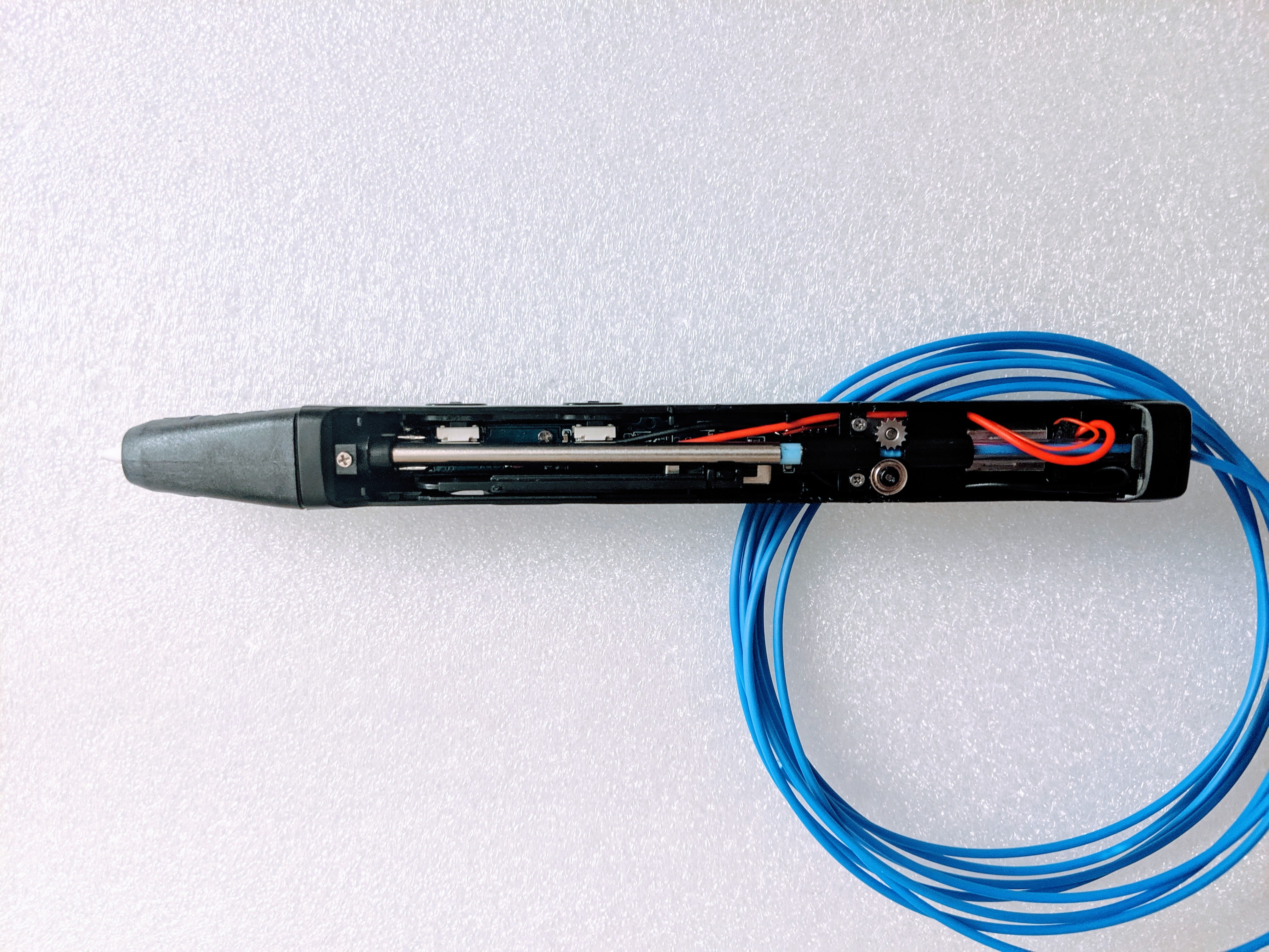
The next experiment I did was developing a quick high voltage, low current DC power supply using a DC-DC high voltage converter (PICO 5VV10P) and high voltage optocouplers ( OC 100G) acting as switches. The DC-DC converter provided 0-10kV output proportional to 0-5 V input. A darlington transistor array IC (Toshiba ULN2803A) was used to modulate a 5V regulated power supply using a microcontroller that goes as input to the DC-DC converter as well as to control the optocouplers.
The optocouplers are arranged in a H-bridge configuration ensuring polarity switching at both the leads coming out of the power supply. The DC-DC high voltage converter (PICO 5VV10P) leads to the major rediction in the size of the power supply. On some digging, it seems to have not just using a step up transformer to multiply the voltage but also a Cockcroft–Walton generator kind of arrangement.
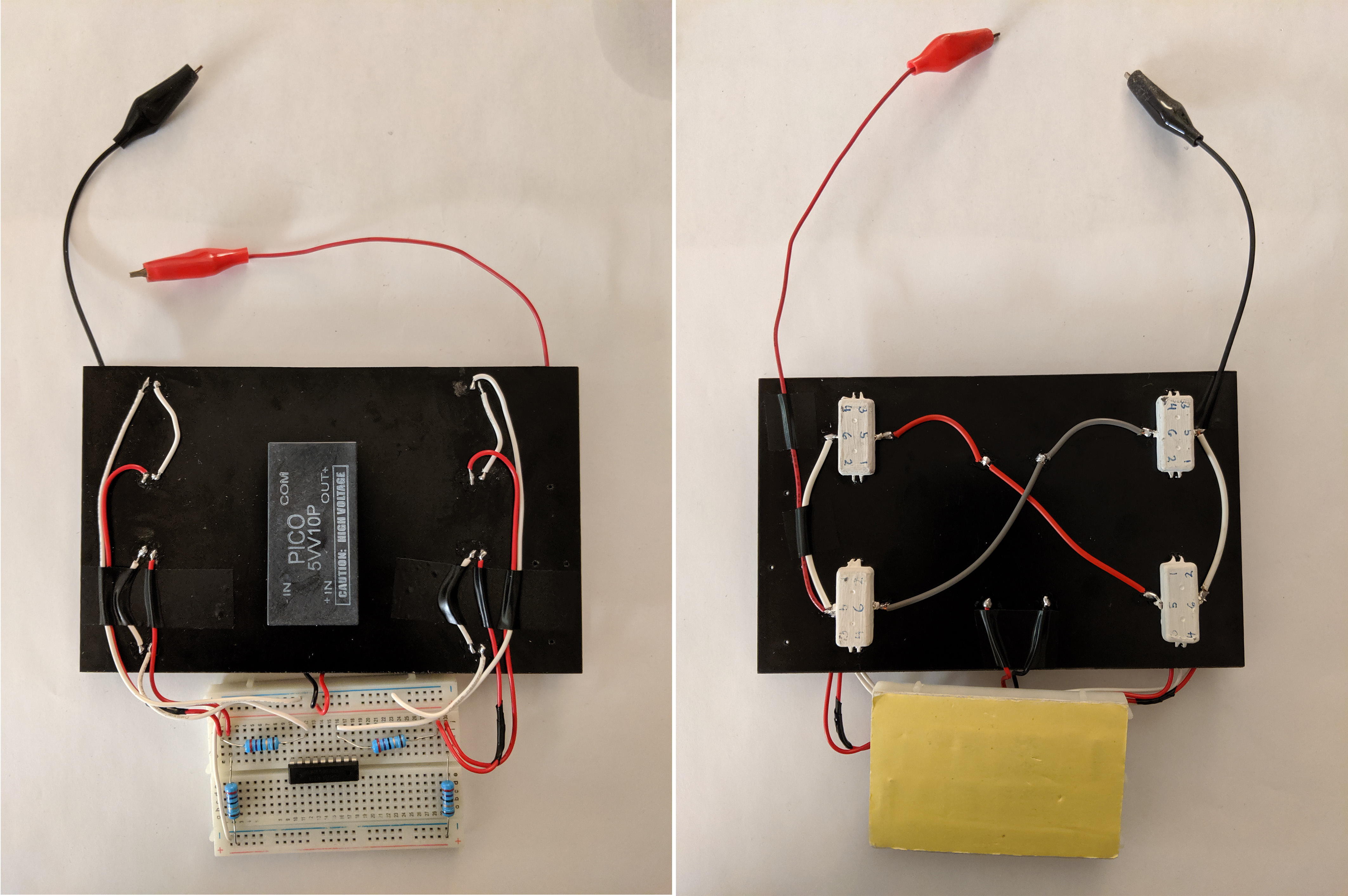
A quick hack for a high voltage power supply using a DC-DC converter. This high voltage cicuit features four optocouplers arrangend in an H-beidge fashion to swich the polarity of the leads (more evident on the right part).
Part 3: Miniaturizing high voltage PCB with more compact DC-DC amplifiers
Continuing the trajectory of innovation, focus shifted towards the development of a high voltage PCB, leveraging an even more compact DC-DC amplifier (EMCO A60P-5). This sophisticated power supply integrated a microcontroller (Arduino Micro), low voltage regulated DC components, alongside the high voltage amplifier and optocouplers, culminating in a harmonious convergence of size and efficiency. This PCB is based on the design by Project Peta-pico-Voltron.
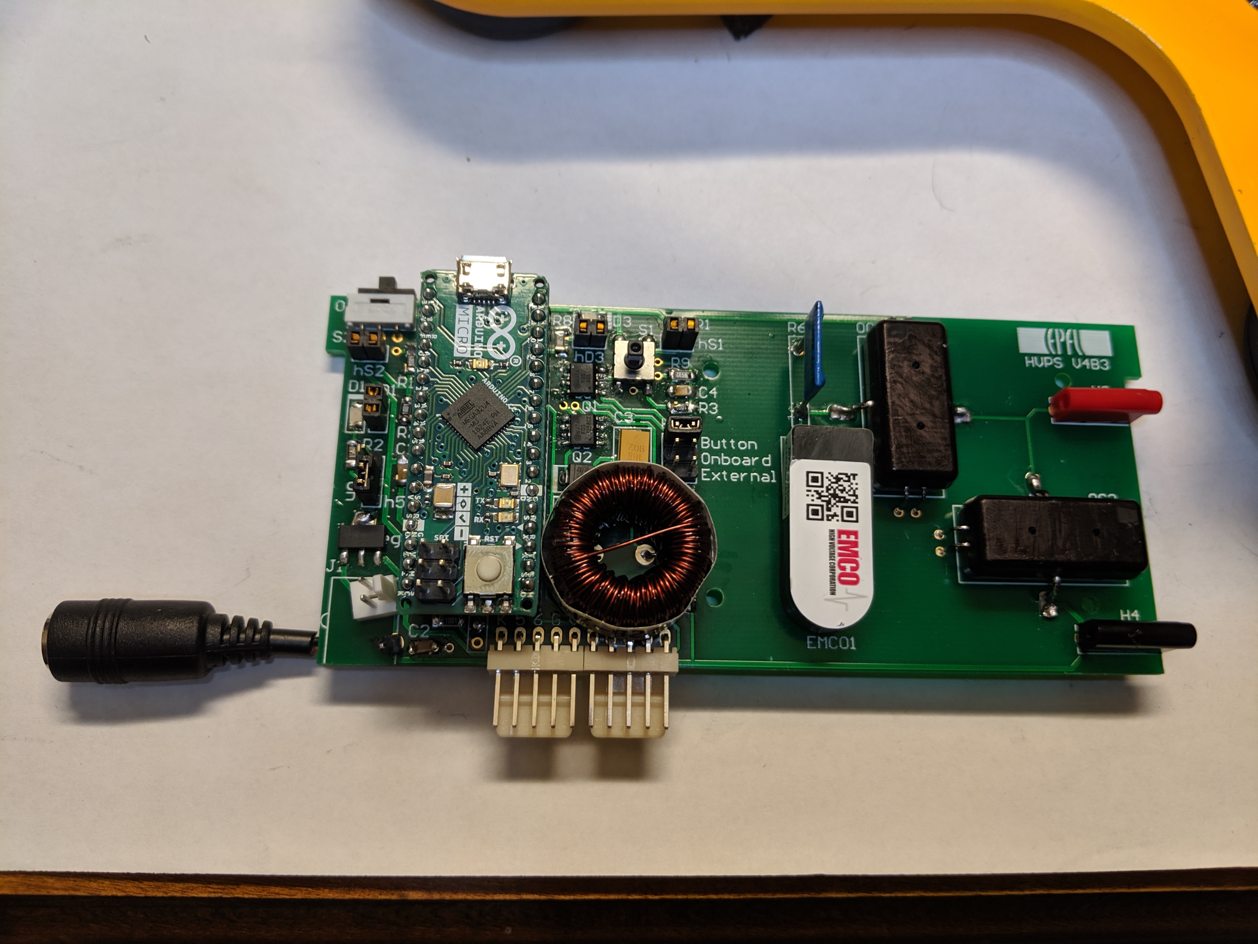
The compact HV PCB uses a tiny DC-DC converter.